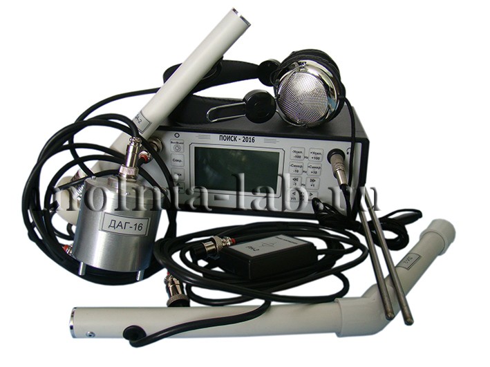
RECEIVER "POISK-2016"
general information
Damage search methods - electroacoustic pulse and induction.
Indication - oscillographic (according to the screen of the graphic liquid crystal display) and auditory (according to the sound in the head phones).
The greatest depth of the cable when determining its route, m, - 10
Error in determining the cable route
(at a depth of 1 m), m, no more, ± 0.05
Maximum cable burial depth when searching for damage:
- electroacoustic method, m - 5;
- induction method ("loop" mode) - 3;
Error in determining the location of damage (with a cable depth of 1 m), m, no more:
- electroacoustic method, m - 0.25;
- induction method ("loop" mode) m, - 1
Acoustic amplifier parameters
DB Gain - Adjustable from 0 to 100
Number of adjustment steps - 100
Bandwidth at the level of 3 dB, Hz - 150 - 3000
Input resistance, MOhm, - 10
|
Pos. |
Name |
Qty. |
Note |
|
1 |
Receiver "POISK-2016" (POISK-2016) |
1 |
|
|
2 |
Acoustic soil sensor DAG-5 (DAG -5) |
1 |
For work on the ground |
|
3 |
Acoustic cable sensor P805-DA2 (P805-DA2) |
1 |
For work on an open cable. Installed on an insulator |
|
4 |
Induction sensor P805-DI2 (P805-DI2) |
1 |
|
|
5 |
Induction attachment frame RN-2 (RN-2) |
1 |
For open cable operation |
|
|
Manual potential electrode EHP |
1 |
|
|
6 |
Sensor handle |
1 |
Collapsible |
|
7 |
Headphones |
1 |
Improved. R ~ (16 ÷ 64) Ohm |
|
8 |
Charger adapter |
1 |
Power supply + 12V, 1A, stab. |
|
9 |
Receiver bag |
1 |
|
|
10 |
Accessory bag |
1 |
|
|
11 |
Manual |
1 |
PO-06-1.00.00.00RE |
The POISK-2016 receiver (hereinafter referred to as the receiver) is designed to search for damage of any type in any power cables with a voltage of 0.4-35 kV by electro-acoustic and induction methods.
The text uses the following terminology and abbreviations:
-
MP - place of cable damage;
-
GOZ - a dead single-phase short circuit of the cable core to the sheath (a short circuit in which there is no spark in the presence of voltage on the cable, and the transition resistance of the MP is within 0-1 Ohm);
-
IP - spark breakdown of the cable core to the sheath (breakdown in which there is a spark in the presence of voltage on the cable, the transient resistance of the MP exceeds 10 Ohm, and the breakdown voltage is within 1-50 kV);
-
GAUV - generator of acoustic shock waves (high-capacity electric high-voltage capacitor, periodically discharged onto the tested cable);
-
GZCH - audio frequency generator;
-
LCD is a liquid crystal graphic indicator (display) used in the receiver.
The receiver can be used:
-
to determine by the electroacoustic method the location of damage to underground power cables in case of spark breakdown of the core to the sheath (MP type IP);
-
to determine by the electroacoustic method the location of damage to underground power cables with a blind single-phase short circuit of the cable core to the sheath (MP type GOZ);
-
for solving the problem of choosing a specific cable from a bundle of open cables using the electro-acoustic method;
-
determining the places of poor contact of the sheath with the cable box;
-
determination of the cable route and search for the place of damage by the induction method;
-
determining the depth of the cable;
-
determination of the place of leakage in the insulation of the XLPE cable sheath or gas pipeline by a potential method at DC and AC voltage;
-
determination of the place of leakage in the insulation of the core of the low-voltage cable to the ground by a potential method.
The receiver is designed to work as part of mobile electrical laboratories, which include a generator of electroacoustic shock waves (GAUV) with the following parameters:
-
storage capacity for determining the location of damage of the type GOZ-300 - 400 uF. at a charging voltage of 5-10 kV;
-
pulse frequency 0.2-1 Hz.
This variant of GAUV is suitable for searching for damage such as GOZ.
To determine the damage of the MT type - the storage capacity can be reduced to 1-5 μF.
In addition, for tracing the cable under test (i.e. determining the route of laying the cable on the ground), an audio frequency generator with a power of at least 20 W with silicified frequencies from 160 to 10000 Hz is required (for example, a GZCH-2500 generator).
To determine the locations of damage in cables of the phase-to-phase circuit type, you will need an audio frequency generator with a frequency of 160-10000 Hz, with a power of 100 W (for example, GZCH-2500).
The receiver is designed for operation in field conditions in the range of ambient temperatures from -20 to +40 о С, relative humidity up to 85% and pressure from 600 to 800 mm Hg. Art.
NOTE. The lower limit of the operating temperature is determined by the performance at this temperature of the LCD and the power supply.


